
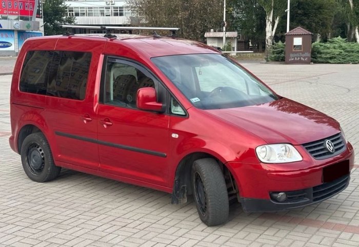
A Volkswagen Caddy that refuses to crank on a wet Monday is rarely an electrical mystery. More often a blade fuse has opened, a relay has tired, or a heavy link beside the battery has failed. The third-generation van, chassis Typ 2K, ran from 2004 through the 2010 facelift and into 2015, and it scatters that protection across several holders. Once those holders are familiar, the job shrinks to a torch, a fuse puller and the card on the lid.
Two boxes? Not quite
Workshop talk still calls the Caddy a two-box vehicle. That description is nearly right, and the gap is where an hour disappears. Volkswagen letters three holders: A (SA) on the electronics box at the left of the engine bay, B (SB) in the same compartment, and C (SC) behind the dash end-cover on the driver’s side of a left-hand-drive van. A separate relay carrier lives in the driver’s footwell; right-hand-drive vans, and many taxis or camper conversions, mirror or extend that layout. One published diagram cannot absorb every option code, which is why two careful manuals sometimes conflict and both remain defensible.
The links beside the battery
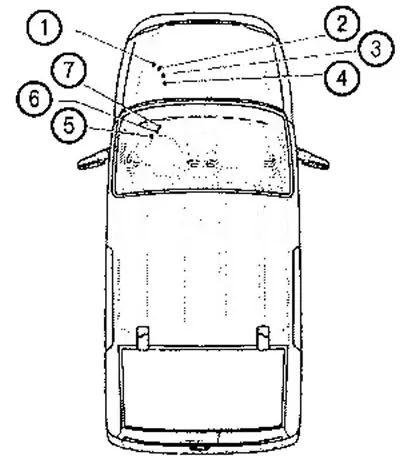
Heavy current never sits in the colour-coded row that photographs well. Holder A is a strip of MIDI-style fusible links bolted beside the battery. On a typical 2008–2010 car, position 1 is 150 A with a 90 A or 110 A alternator, and 200 A when the alternator is rated 140 A; position 2 carries 80 A for electromechanical steering module J500 and motor V187. Position 3 is 50 A for radiator-fan control unit J293. Position 4 is the awkward designation: 50 A on vans with central locking, 80 A without, supplying onboard-supply control unit J519 and, where locking is fitted, X-contact relief relay J59. Position 5, commonly 100 A, feeds a large group of fuses on holder C. Vans with the PTC auxiliary air heater add position 6 at 40 A for low-heat relay J359 and position 7 at 80 A for high-heat relay J360, both protecting element Z35. A shorted heater opens those links on a November morning and leaves the rest of the van looking fine.
Faults that live in the engine bay
Holder B is where ordinary faults declare themselves, and the rating follows the engine code, so the printed ampere value beats any forum photograph. On the familiar pre-facelift layout, SB3 is only 5 A for J519, while SB4 is 30 A for ABS module J104. Later cards often show 20 A nearby for that module and the hydraulic unit — the contradiction that fits the wrong blade. SB5 is commonly 15 A for dual-clutch mechatronics J743, though some gearboxes, including the 0AM, call for 30 A. SB7 at 40 A feeds terminal-15 relay J681; SB8 at 15 A covers radio and navigation; SB10 is 10 A in 2008–2010 and 5 A on several later lists. SB13 is the engine computer, 15 A on many petrol units and 30 A on diesel injection, while SB14 at 20 A supplies petrol coils and SB15 at 5 A watches the fuel-pump relay and diesel glow control. SB19 at 30 A is the front wiper, and SB16 with SB26 — often 30 A and 40 A — feed J519 for the headlamps. Vacant sockets are intentional, not missing fuses.
Arguments start under the dash
Under the dashboard, holder C becomes a thicket of miniature blades, and the arguments start here. Which position is the cigarette lighter? It is widely designated SC47 at 25 A. The 12-volt socket beside the handbrake, together with the load-compartment socket, often shares SC42 at 15 A or 30 A according to equipment. Airbag supply appears as 5 A, commonly on SC6 and again near SC9; fitting a 10 A just to test is a poor bargain. Comfort control, the module behind central locking and much of the window logic, is frequently SC50 at 25 A, while blower supply sits in the 25–40 A band and SC35 at 40 A is a regular candidate. Rear-wiper protection is a modest 15 A on many cards, and trailer recognition can be 20 A. None of these figures is legislation: the legend on that cover, read against the van’s equipment, outranks every general article, including this one.
The case number is not the slot
Relays speak two dialects at once. The workshop designation is a J-number, while the figure moulded into the housing — 53, 449, 460, 644, 645 — names the relay family, not the socket. B1 is J681, terminal-15 supply relay 2, family 460; B4 is J689, terminal-30 supply relay 2, family 449; B5 is J9, heated rear window, family 53; B6 is J413, the horn, also family 449. B7 and B8 are double washer-pump relays J729 and J730, B9 is J59, the X-contact relief relay, and B2 with B3 frequently stay empty. The footwell and the engine-bay carrier add fuel-pump relay J17, glow-period module J179, starter relays and, on certain petrol engines, the secondary-air pump relay. A horn relay and a supply relay can share the number 449 and still refuse to interchange, because function and pin layout decide the swap.
Colour is a hint, not a verdict
Blade colour remains a cross-check, never a diagnosis. Tan denotes 5 A, red 10 A, blue 15 A, yellow 20 A, white 25 A, green 30 A and orange 40 A; once sunlight has bleached the plastic, the stamped numeral wins. Raising the rating to limp back only moves the failure into the loom, since the fuse opened when the circuit demanded more than the cable was built to carry. The wiring notes on vwmanual.ru were a genuine help while the 2005-on layout was being checked — those diagrams letter the holders as Volkswagen does — so set the page beside the lid card and prove the circuit with a meter.
On the ramp the order stays plain. Name the function that died, then decide whether its supply is a battery link, an engine-bay blade or a dash blade. Read the ampere rating and the J-code for that engine and that year, because May 2009 and the 2010 facelift both rearranged positions. Fit the same rating, seat the relay until it clicks, and only afterwards chase wiring. The Caddy 3 is not electrically fragile. It is poorly served by one screenshot passed off as every van’s card.